Quick Start Guide
For this guide we will create a simple test run that identifies the device, assigns it an ID and runs 2 tests.
The device we will test will be a an Arduino with a demonstration scetch that you can download
here. The application has been tested and is known to work int the google chrome browser.
Note
In this guide, device under test will be referred to as DUT.
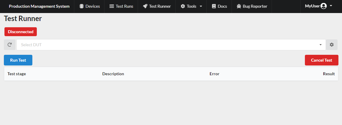
When you log in, you are greeted with the test runner page. This is where the tests will be run in the production environment.
Assuming this is your organization’s first login, there are no devices that have been set up and no test configured. Let’s get started using the system. The first thing to to is to create a device.
Create a new device
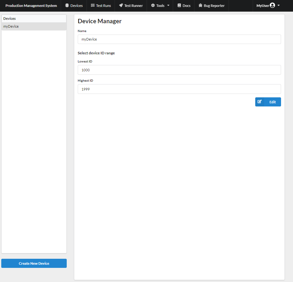
To create and manage all your types of devices you will use the device manager tool. You can access it from the navigation menu at the top of your screen by going to Tools -> Device Manager. You should then be greeted with the following page.
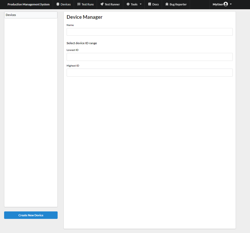
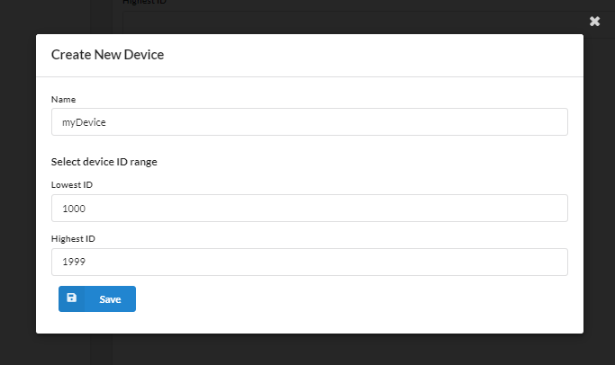
To create a device simply selects the Create New Device button in the lower left corner of your screen a small form will appear.
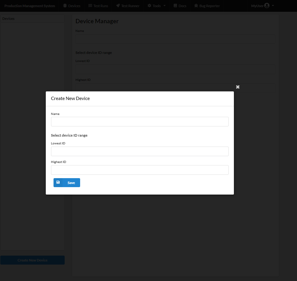
Now fill in the form with the a name of the device and a range of IDs that the device will have in production. The system assigns the DUT an ID in production from the set range in the device manager. That is when tests are executed on the Test Runner page. The first device tested will be assigned the lowest ID and the assigned IDs will increment for each new device tested. The ID range of one device type will not conflict with the ID range of another device type. The device type and device ID are used together to identify the device. You can choose whatever range of integer IDs you would like.
Note
Currently there is only support for integer IDs. Other ID types such as UUID are on the roadmap.
The figure below shows the new device form filled out. For this quick start guide we will call the device myDevice
Now save the new device. It will appear in the device list on the left on the screen and its configuration will be displayed. If you make any mistake you can always edit the device
Warning
Be careful changing the device. It will affect all the tests and data you will have generated. That may or may not be what you want.
Now that we have successfully created our first device we need to create a test config that tells the system how to execute the test.
Create a test config
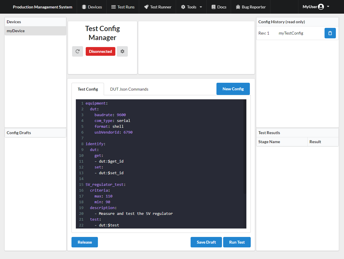
The test config is what tells the system how to perform the test for you DUT. To create a test config we use the Config Manager tool. Go to navigation bar and select Tools and Config Manager in the drop down menu.
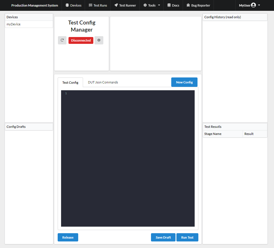
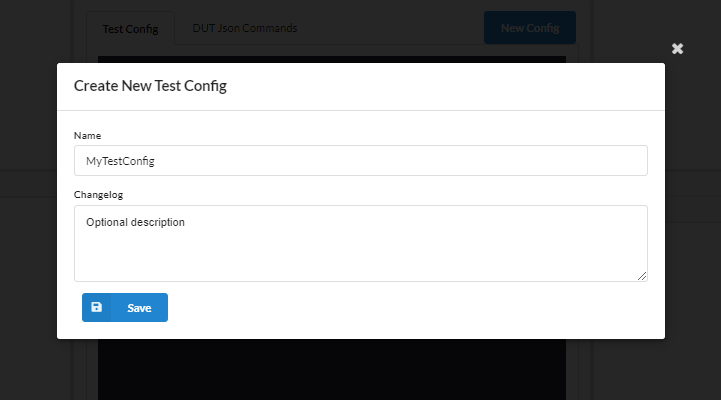
To create a new test config select the device you want to create a test config for from the Device table in the left top corner and click on the New Config button. This will open a form that will ask you to enter a name and changelog. Give the new config a name, the name is only for you. The name is not used to identify the config. In the changelog dialog, you can optionally add some description.
Now press the save button and you will see that the new configuration has automatically been selected in the Config Drafts table and a Configuration template has been added to the text editor. We will use the text editor to edit and write our test config.
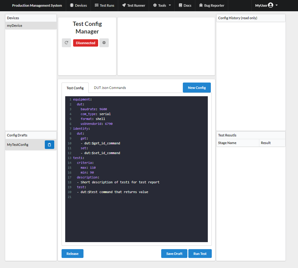
The Config Drafts table lists all the test configs that are being worked on and you can select witch one you want to edit. From a draft you can release a config that will then be displayed in the Released Config History table. (More about that in Release config). Additionally, from the Config History table you can save a copy of the released config as draft, save changes and releases a new version. Now lets edit the template configuration to create a test run for myDevice.
Note
The test config is written in YAML. That means that the formatting is important. The indentation needs to be consist throughout the configuration.
Config structure
The test config is written in yaml and has 3 layers. Stage, entry and parameters. They follow the format
1stage:
2  entry1:
3    parameter: some_value1
4    parameter: some_value2
5  entry2:
6    parameter1: some_value1
7    parameter2: some_value2
The highest level is the stage and there are a number of built in stages. These stages are equipment and identify. All other stages will be considered a test stage. There can be any number of test stages with in a config and can have arbitrary names.
setup equipment stage
To start with we need to define and configure the equipment that will be used for the test. For our Arduino test setup, we can use the equipment config from the template already in the text editor.
1equipment:
2  dut:
3    baud-rate: 9600
4    com-type: serial
5    format: shell
6    usbVendorId: 6790
Lets dissect the above configuration. Everything under the equipment: *block defines how the system connects and communicates with the equipment and DUT in the test run we are configuring. Under the *equipment: * block we define a block for each type of equipment or device we need. In the above configuration, we have only defined the **dut*. dut is the only keyword equipment name and it should be used for the DUT. The dut name is used for the identification proses to distinguish the DUT from other equipment used during the test.
Note
Currently the only communication type supported is serial. There are 2 different formats available for the serial interface, json and shell. For further information on the formats, take a look at the serial interface documentation. For this guide we will use the shell format as it is Easier to setup but at the cost of less flexibility.
The parameters specified for the equipment dut define the communication with the equipment and how it is identified.
com-type: Defines the communication method used with the equipment. In this case, we use a serial interface. The rest of the parameters are all serial interface configurations.
baud-rate: Sets the baud rate of the serial communication.
format: This sets the communication protocol or format that will be used on top of the serial interface. We will be using the shell format. See serial interface documentation.
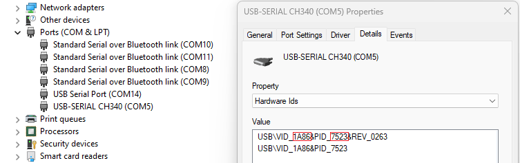
usbVendorId / usbProductId: These parameters are used to identify the communication interface to distinguish between connected equipment. Only one of these parameters are needed per equipment.
To get the usbProductId and usbVendorId on Windows you can open the virtual COM port properties in your device manager. Select the Details tab and select the Hardware Ids From the drop down menu. There you will see VID for usbVendorId and PID for usbProductId as shown in the figure below.
Command strings
In the test config, you can configure what device receive what command during the test execution. This is done within the command string. A command string is what you Write in the test config to send commands to the equipment. They have the following format.
equipment_name :$ message_string
Where equipment_name refers to the name defined in the equipment stage in the config. (See setup equipment stage). The “: $” characters are used to separate the equipment name from the message string. And the message_string is the string sent over serial to the equipment specified by the equipment_name.
Note
All spaces are removed from the command string before sending the command to the DUT/equipment.
The serial shell format
Messages sent to the DUT/equipment are in the format
command|argument_1|argument_2
The message is a single string without tabs or spaces and terminated with a new line character. The shell format has built in support for command arguments separated by the ‘|’ character. The command should be the first part of the message followed by optional arguments. If no arguments are used, then there should be no ‘|’ character. For commands that supply generated values, such as the set_id entry in the identify stage, the system will add the generated value as an argument.
Received messages from the DUT/equipment are in the format
ok|return_value
Where ok is an acknowledgement form the device that the command executed successfully. Alternatively, the acknowledgement can be error. After the acknowledgment there is an ‘|’ character separation The return value from the acknowledgement. The return value can be an integer or string depending on the command. For logic response use 0 or 1.
Setup identification stage
The identification stage is used to get an ID from the DUT and to assign an ID to the DUT. You can additionally get an ID from a sub assembly within the DUT. Let’s take a look at the template configuration and what we need to change.
1identify:
2  dut:
3    get:
4      - dut:$get_id_command
5    set:
6      - dut:$set_id_command
Under the identify stage we define each device/sub-assembly we want to get the ID from. The only mandatory device is the dut and it should be the only device with a set command. It is the only device that can be assigned an ID during a single test run, other sub-assembly under the identify stage are to assonate an sub-assembly with the device. All other devices should already have an ID assigned. If the DUT has not been assigned an ID, it should return the string “null” to indicate no ID as has been assigned. Under each device defined in the identify stage, there should be a get: entry with a single command string. The get ID command should return the ID or the string “null”. Only if no ID has been assigned will the set command string be executed.
Now for the identify configuration needed for our demonstration Arduino. The Arduino sketch both have a set and a get command. They are get_id and set_id. So we need to update our config to the following
1identify:
2  dut:
3    get:
4      - dut:$get_id
5    set:
6      - dut:$set_id
Optionally, you can add a setup entry to each device in the identification stage. This is a list of commands you can send to the device to prepare it for the ID set and get commands. Below is an example of how the setup entry is used. This is not needed for our Arduino sketch.
1identify:
2  dut:
3    setup:
4      - dut:$power_on_eeprom
5      - dut:$as_many_commands_as_needed
6    get:
7      - dut:$get_id
8    set:
9      - dut:$set_id
As mentioned in The serial shell format, arguments are automatically added to commands when the system provides the required information. In this case, the system generates an ID and adds it to The set command. For example, let’s say the generated ID is 1000445, that would mean the set command sent to the device would be set_id|1000445.
Add a test case (test stage)
Now that the equipment is set up and devices identified. Let’s get to work on the actual tests, the point of all this work. The test stage can have any arbitrary name as long as it does not Interfere with the built in stages. From the template we started with we have bellow test stage in the test config. In this case, the test is named test1 but we will change that later.
1test1:
2  criteria:
3    max: 110
4    min: 90
5  description:
6    - Short description of test1 for test report
7  test:
8    - dut:$test command that returns value
There are three optional entries, setup, destroy and description. It is highly recommended to give each test a good description. It will become part of the test report and will give much needed context when reviewing the test reports. Under the description entry, there should be a single string that contains the description as can be seen in the template config. The second optional parameter, setup allows you to send a list of commands to the device/equipment be for running the test and destroy allows you to send a list of commands after running the test command. The setup and destroy entry can look like the following.
1setup:
2  - dut:$power_on_eeprom
3  - dut:$as_many_commands_as_needed
4
5destroy:
6  - dut:$power_off_eeprom
7  - dut:$as_many_commands_as_needed
The test stage has two mandatory entries, criteria and test. The criteria set the test criteria. There are three supported options for the criteria, min, max and equals. Min and max can be used in conjunction, but the equals parameter has to stand alone. In the above configuration, the test will fail if the returned value from the DUT is above 110 or below 90. The test will only pass if the returned value is between the min and max parameters including the parameter values. It is possible to use only the max parameter or only the min parameter when needed. The equals parameter has to be the only criteria when used. Min and max will preempt the equals parameter. When equals are set, the returned value from the DUT must be exactly the same as the parameter or the test will fail. Below is an example of a criteria entry with the equals parameter set.
1criteria:
2  equals: 10
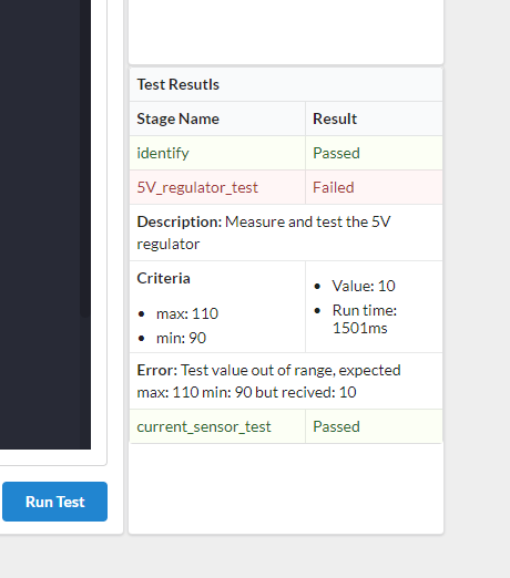
In the above example, the return value from the test entry must be exactly equal to 10. Now lets take a look at the test entry of the test stage. There should only be a single command string under the test entry. This command should return an integer value as described in The serial shell format. The returned value is then compared with the criteria parameters to determine if the test has passed or failed. For our demonstration Arduino sketch we need to make a few changes. The Arduino sketch currently only Supports one test command, the string “test” that will return the integer 10. We will additionally change the test name and update the description. Lets say we are testing a voltage regulator. For our purposes, we don’t need the setup or destroy entries. So our test stage config will look like.
15V_regulator_test:
2  criteria:
3    max: 110
4    min: 90
5  description:
6    - Measure and test the 5V regulator
7  test:
8    - dut:$test
We expect this regulator test to fail because of the return value of 10 from the ‘test’ command is outside the min and max parameters. Let’s add one more test to our config. This time, we will use the ‘equals’ parameter in the criteria. Let’s say we are testing a current sensor. In a real application, here we might want to use the setup entry to enable a calibrated current source and then the destroy entry to disable the current source. But for our demonstration purposes, we will keep this simple and only use the criteria, description, and test entries. The test stage could then look like this.
1current_sensor_test:
2  criteria:
3    equals: 10
4  description:
5    - Test current sensor by measuring calibrated current source
6  test:
7    - dut:$test
We expect this test to pass because the return value from the ‘test’ command is equal to 10. If we now put this together in the entire config, we get:
 1equipment:
 2  dut:
 3    baud-rate: 9600
 4    com-type: serial
 5    format: shell
 6    usbVendorId: 6790
 7
 8identify:
 9  dut:
10    get:
11    - dut:$get_id
12    set:
13    - dut:$set_id
14
155V_regulator_test:
16  criteria:
17    max: 110
18    min: 90
19  description:
20    - Measure and test the 5V regulator
21  test:
22    - dut:$test
23
24current_sensor_test:
25  criteria:
26    equals: 10
27  description:
28    - Test current sensor by measuring calibrated current source
29  test:
30    - dut:$test
Now that we have edited the config in the text editor as shown above, we must save the config draft by pressing the Save Draft button located at the lower right of the text editor. A changelog form will pop up; note down what you have changed and press the Save button. Remember to save your config drafts regularly while you work on them to ensure that you don’t lose your work. Note that when running a test config in the config manager the runner will execute the current code in the text editor, that is you don’t have to save a config to test it.
Test the new config
For this step you need to have uploaded the demonstration Arduino sketch (mentioned at the beginning of the guide) to an Arduino and connect it to the computer you are using for this guide.
First time connection
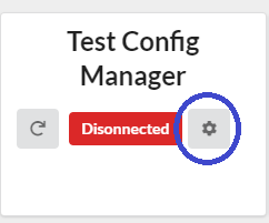
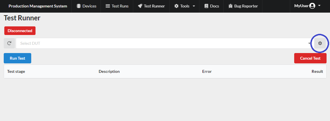
Before you can run the test, you need to allow your browser to connect to the device/equipment. You can do this from either the config manager or the test runner pages. Open up the connection manager dialog by pressing the setting icon next to the dis/connection icon in the config manager or next to the device selection drop down in the test runner.
In the config manager
In the test runner
Once you press the button, you will see the connection management dialog where you can add devices/equipment that your browser can have access to. This will only have to be done once for each computer. The dialog lists all the equipment defined in the current config in the editor. It will read the config directly from the editor, so there is no need to save the config between editing the equipment config when debugging. You can also use the connection refresh button located on the left of the dis/connect icon to refresh all the connections.
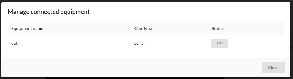
Click on the Add button for all the devices/equipment you have configured. A pop up dialog will appear that should list the available USB connections with the configured usbVendorId or usbProductId. The list in the dialog is filtered based on the USB ID parameter used. If the dialog is empty make sure to check the usb id you are using in the config.
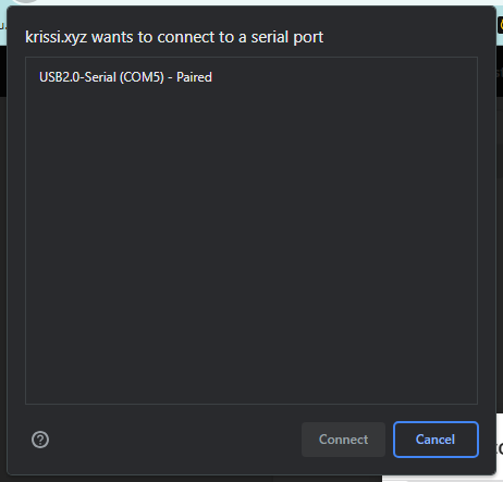
Select the connection you need and click on connect.
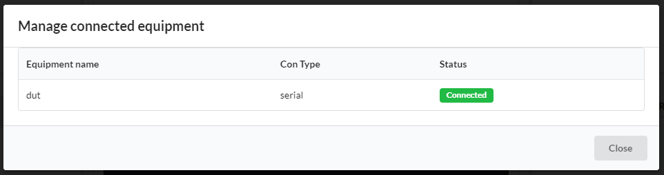
The connection manager dialog should now show the status of the equipment you added as connected as shown in the figure above. Once all your equipment is connected, close the connection manager dialog, and you are ready to start running tests. The disconnected icon should change to connected once you press the refresh connection button.
Testing the config
You can test your config in the config manager by pressing the run test button on the bottom right in the text editor. If you have set up the equipment as described in Setup equipment stage, all the connections should automatically refresh, and the test should start executing. The result table on the right of the text editor will populate with the test results.
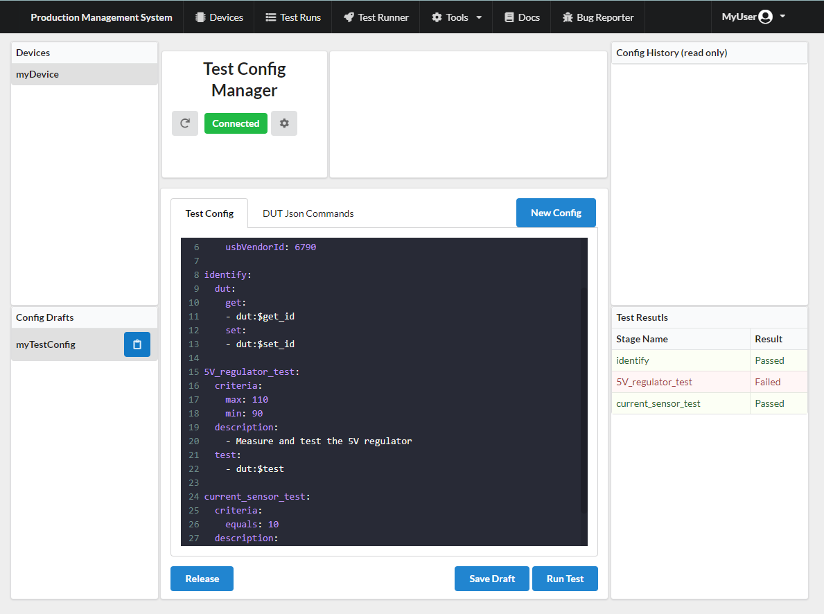
You can click on the rows in the result table to get more detailed information on each test stage.
Release config
Once you are happy with your test config and want to start using it in production, you need to release the config so the test runner can use it. Click on the release button on the left below the text editor. A dialog should appear that displays the accumulated changelog from all the saved drafts for the selected config. You can only release a config that has been saved. A warning message will appear if there is unsaved config in the text editor.
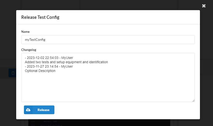
You can now correct the changelog or add to it if you need to. Once the changelog looks good, you can click on release, and the dialog should close. Your config should have moved from the Config Drafts table to the Released Config History table. The config is no longer editable, and the test runner will now use this latest released revision of the test config for this device.
You can save the released config as a draft to continue improving it and release the improvements as a new revision that the test runner will use. The test runner will always use the latest revision of the config.
Using the Test Runner
Now that the config has been released, the device should now be available in the test runner. Open the test runner from the navigation bar. In the dropdown menu, you should now see the device you created in the drop-down list. Select the device, and it should connect automatically.
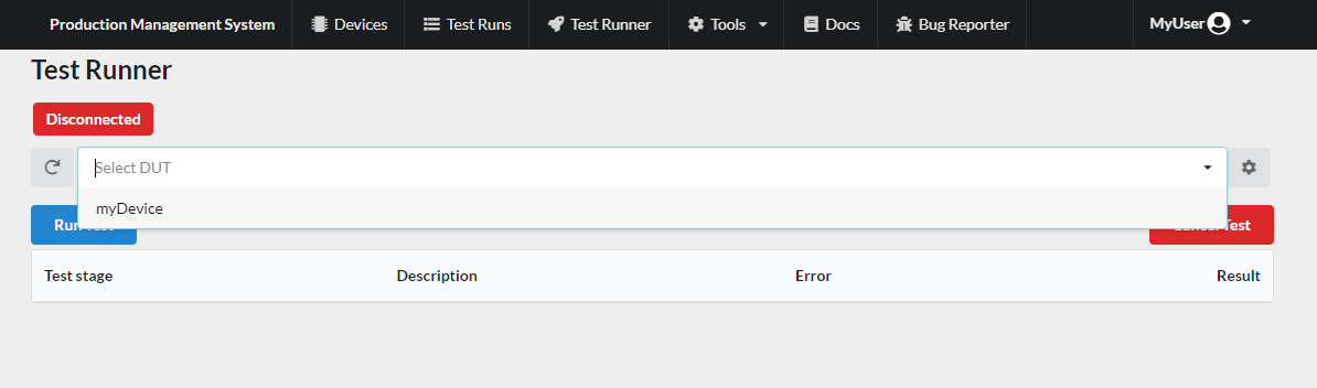
If the connection fails when you select the device, make sure all the equipment you configured is connected and refresh the connections by pressing the refresh button on the left of the drop-down menu. Once the connection indicator shows everything is connected, you can press the Run Test button to run the test. The result table will start to populate with the test stages as they finish executing.
Note
The run test button cannot be pressed while the connection is being established. The button will be faded for a few seconds.
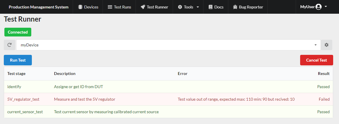
After the test has finished running, the results will be saved to a database and can be viewed from the test list and device list pages. Only the tests run in the test runner will be saved. No test run in the config manager will be saved to the database.
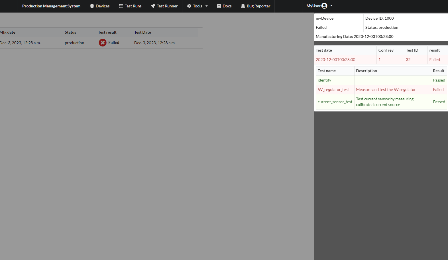
Viewing the results
The results from individual tests can be viewed in the test list page. Open the Test List page from the navigation bar. Simply select a test run from the test list table, and a sidebar will open displaying the results of the test.
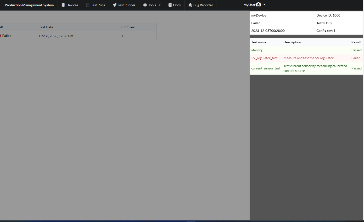
You can also see the entire history of each manufactured device. Open the Device List page from the navigation bar. Select a device in the device table, and a sidebar will appear listing all the test runs that have been performed on the selected device. You can select each test run from the list and view each test report in detail.